

There’s lot of posts and information out there on how to use Naze32 with Sbus but still I found myself having to do a lot of research and guesswork to make it work on my setup. I figured I’d make it easy for the next person with the same gear or at least bring one more puzzle piece to the solution on how to make it work on your setup. In this guide I will go through:
- Setting up the 9xr transmitter
- How to bind your transmitter and receiver
- How to electrically connect receiver and Naze32
- How to set up Naze32 in Ceanflight to use the SBUS as rc input
Here is a list of what gear I use which is used in this guide:
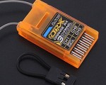
- OrangeRx DSMX Compatible DSMX 3Ch S.BUS 2.4Ghz Rx (twin long antenna version)
- Turnigy 9XR Transmitter Mode 2 (No Module)
- OrangeRX DSMX/DSM2 Compatible 2.4Ghz Transmitter Module (JR/Turnigy compatible)
- AfroFlight Naze32 Acro AbuseMark FunFly Controller (rev5)
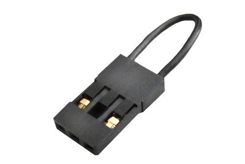
You will need to invert the logic level of the SBUS signal from the reciever to the Naze32. I made my own inverter which I will explain but you would save some time on just buying a premade inverter such as this one recommended by Cleanflight wiki: ZYX-S S.BUS Connection Cable.
It should be noted that it probably doesn’t matter what reciever you use as long as it has SBUS support.
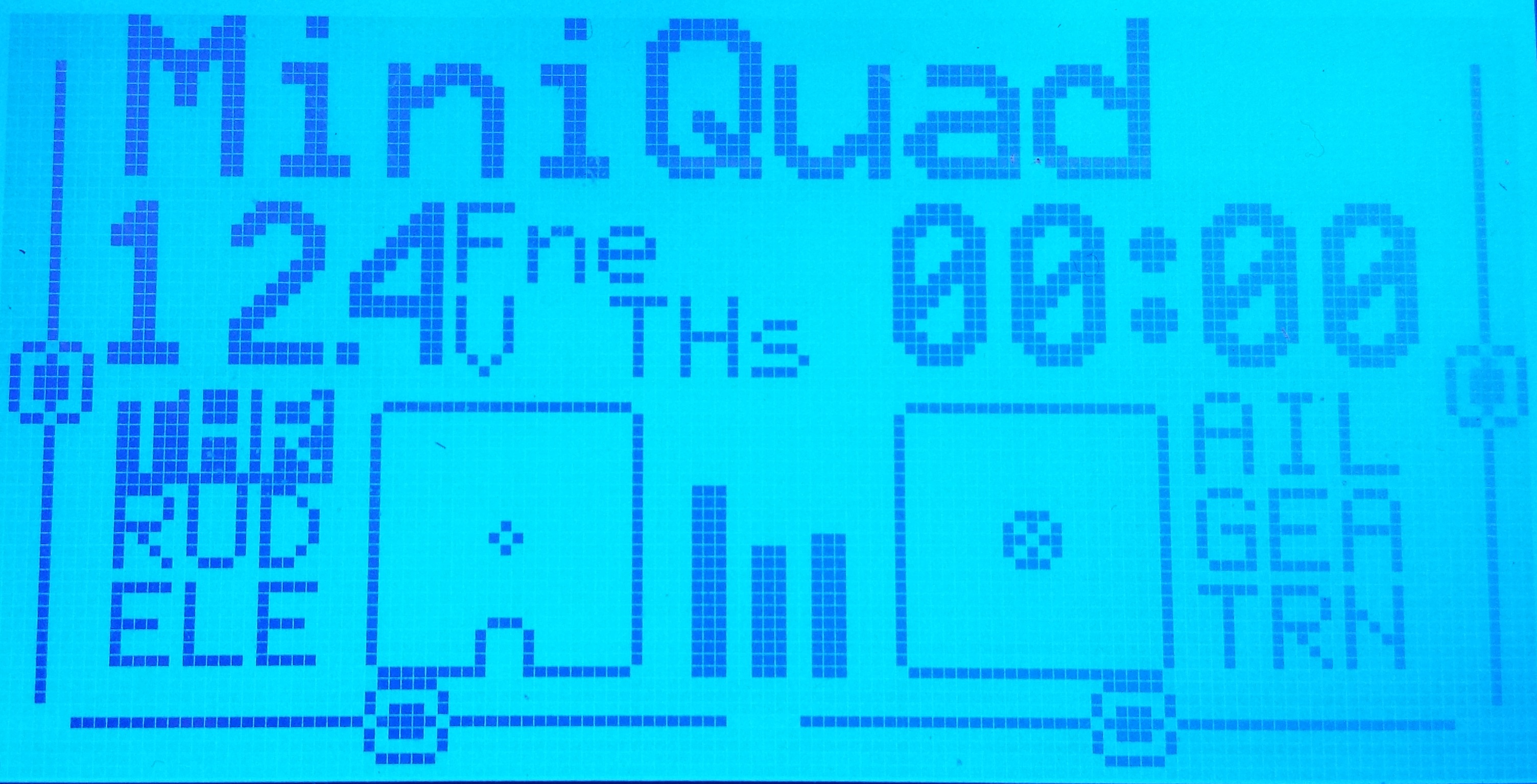
1. Setting up the 9xr transmitter
- turn on the 9xr
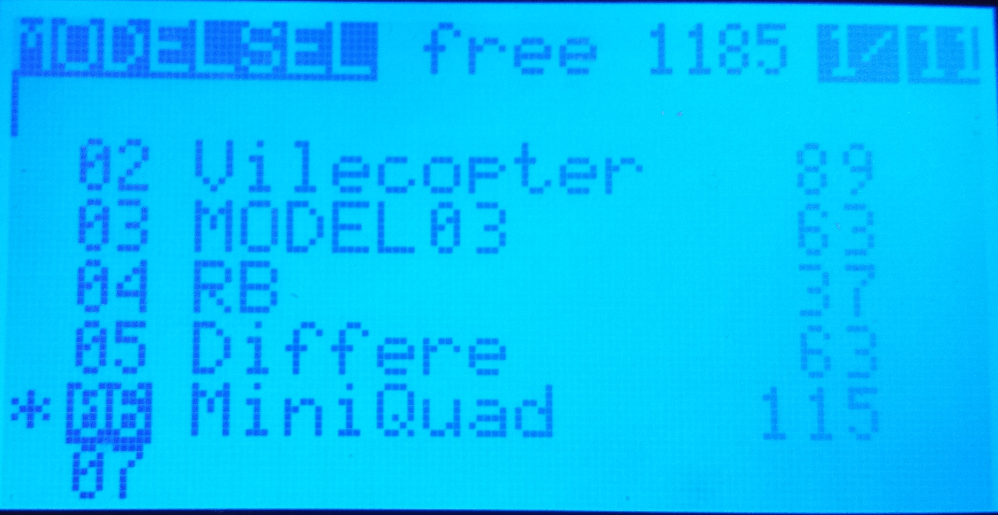
- after the splash screen, press right button
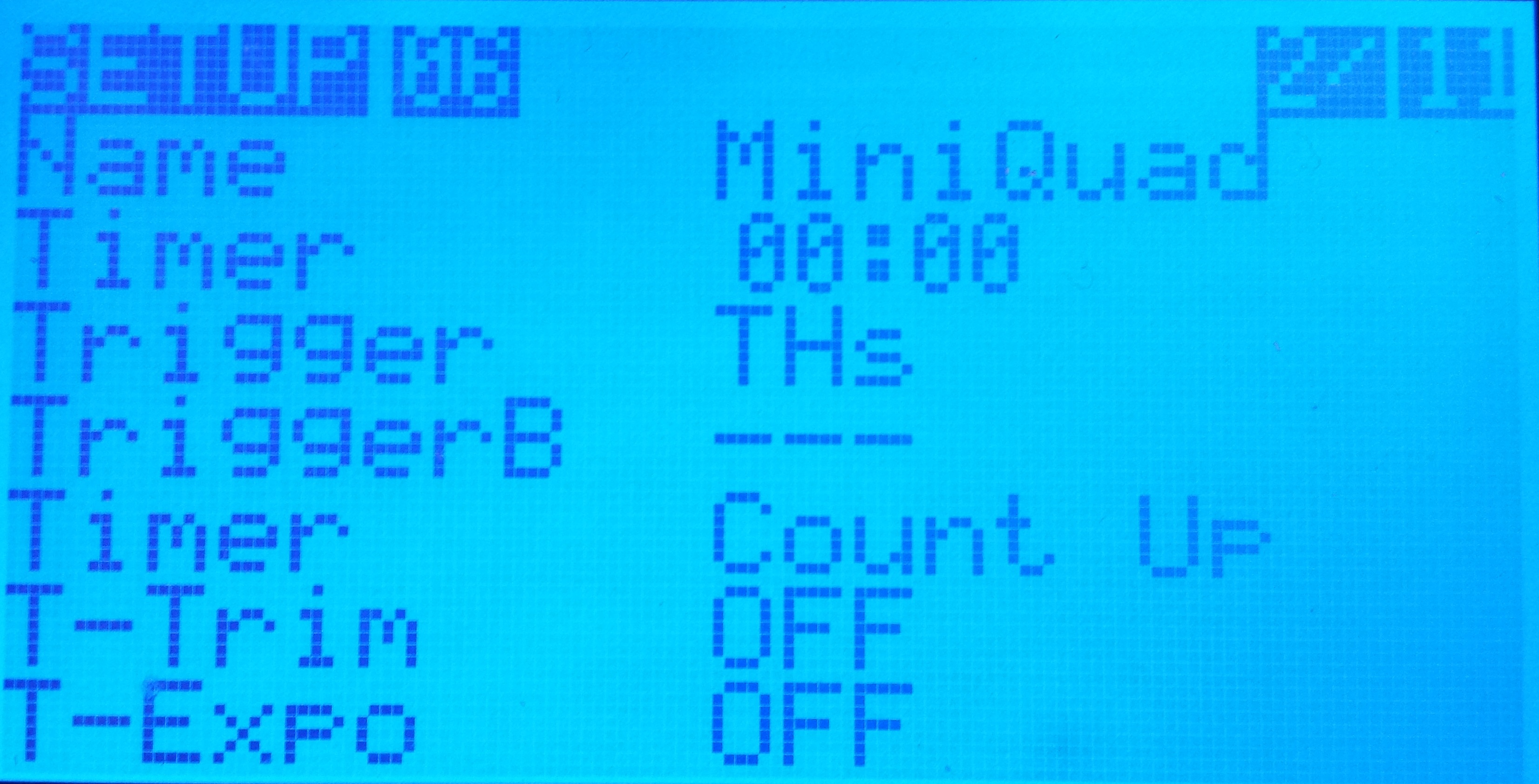
- choose which model to use by pressing right
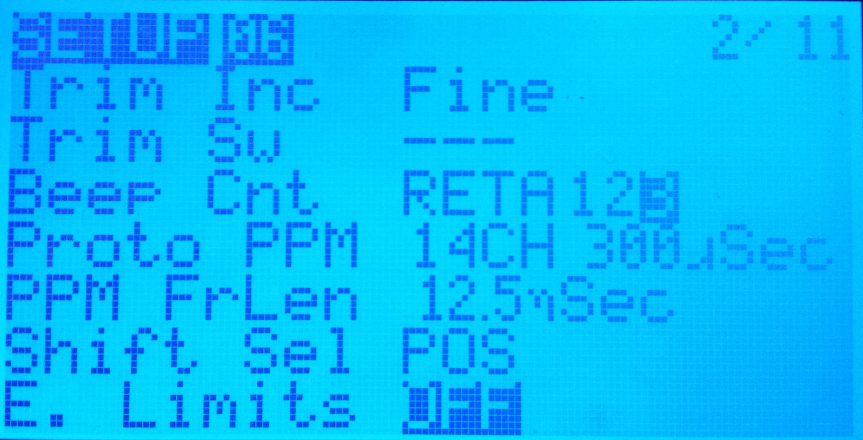
- click right button once so it says “2/11″ in the upper right corner
Change to: ppm, 14ch, 300µSec, 12.5ms
I noted that some settings will make the DSMX module “angry” and then it wouldn’t send anything. if this happens you need to change back to some settings that works and restart the 9xr. If the module makes a high pitch beep(1/2 a second) and blinks green( three quick blinks every 2nd second ish) when it starts it means it’s working fine.
2. How to bind your transmitter and receiver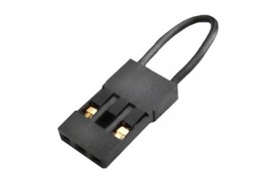
This step is pretty straight forward, but I include it for completeness. You need some +5v and GND to power the receiver. Easiest is to power it from an ESC.
- Start with everything powered off.
- Disconnect the motor from the ESC and make sure the motor leads isn’t touching anything.
- Put a bind plug in the bat/bind port of the receiver.
- power up the ESC by connecting it to a battery
- Plug in the servo lead from the ESC in the receiver in any port on the receiver to power it up. Usually it will blink orange rapidly.
- hold the bind button on the module(the thing in the back of the 9xr) while powering it on. hold until it starts beeping and blinking.
- after releasing the bind button on the module, the receiver will normally turn to a steady light wihin seconds which indicates that the binding is complete.
- switch off the receiver( disconnect from ESC) and remove the bind plug.
- switch off the 9xr.
3. How to electrically connect receiver and Naze32
There will be 3 wires connecting the Naze32 and the receiver; GND, +5v and signal. Either you buy the inverter module, in which case you simply connect it in between the Naze32 and the receiver.
Logic inverter
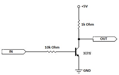
It is possible to build a logic inverter with many different transistors, like a N-channel MOSFET for example. Just google “logic inverter npn” or “logic inverter N-channel MOSFET” or similar depending on what you got available and you will find a schematic.
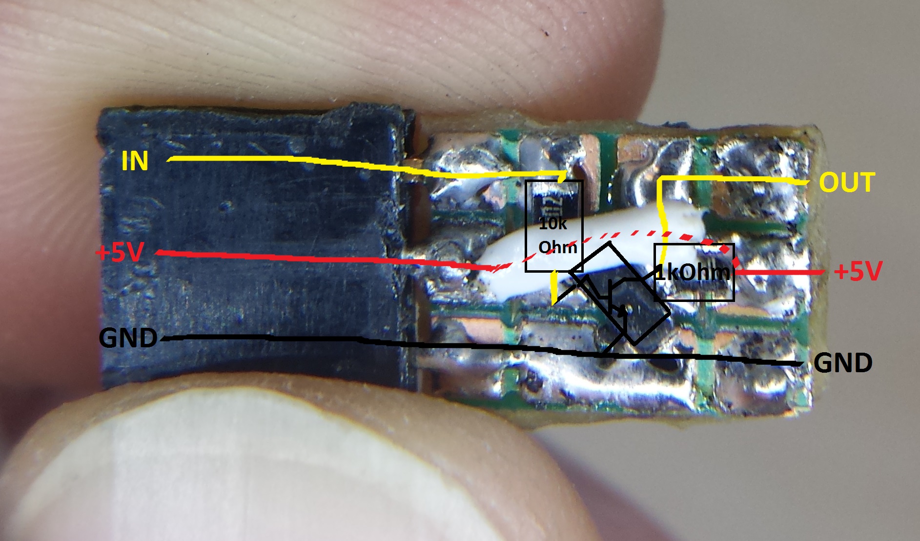
For the inverter I built, I used this NPN transistor, a SMD 1k Ohm resistor and a SMD 10k Ohm resistor. I soldered the components according to this scematic:
-
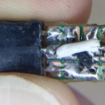
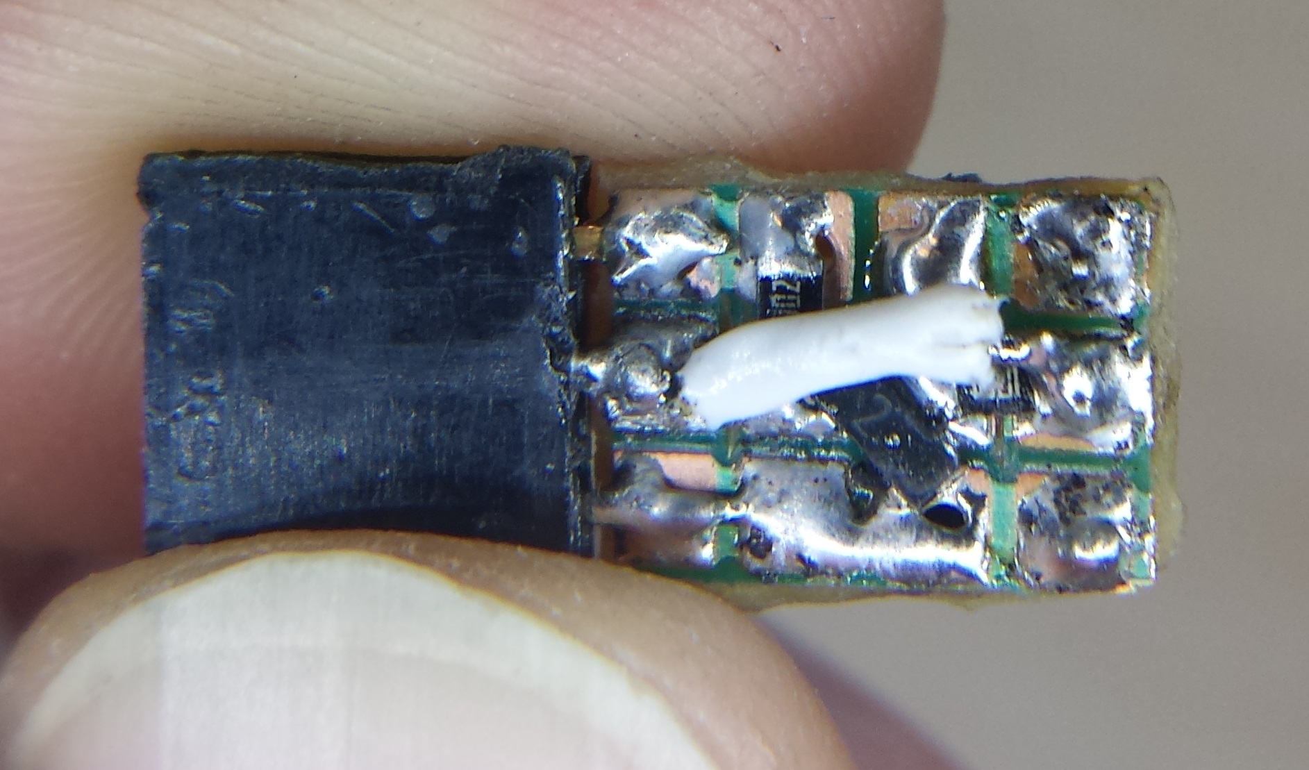
- It’s not the prettiest solder work but it does the job and it’s tiny.
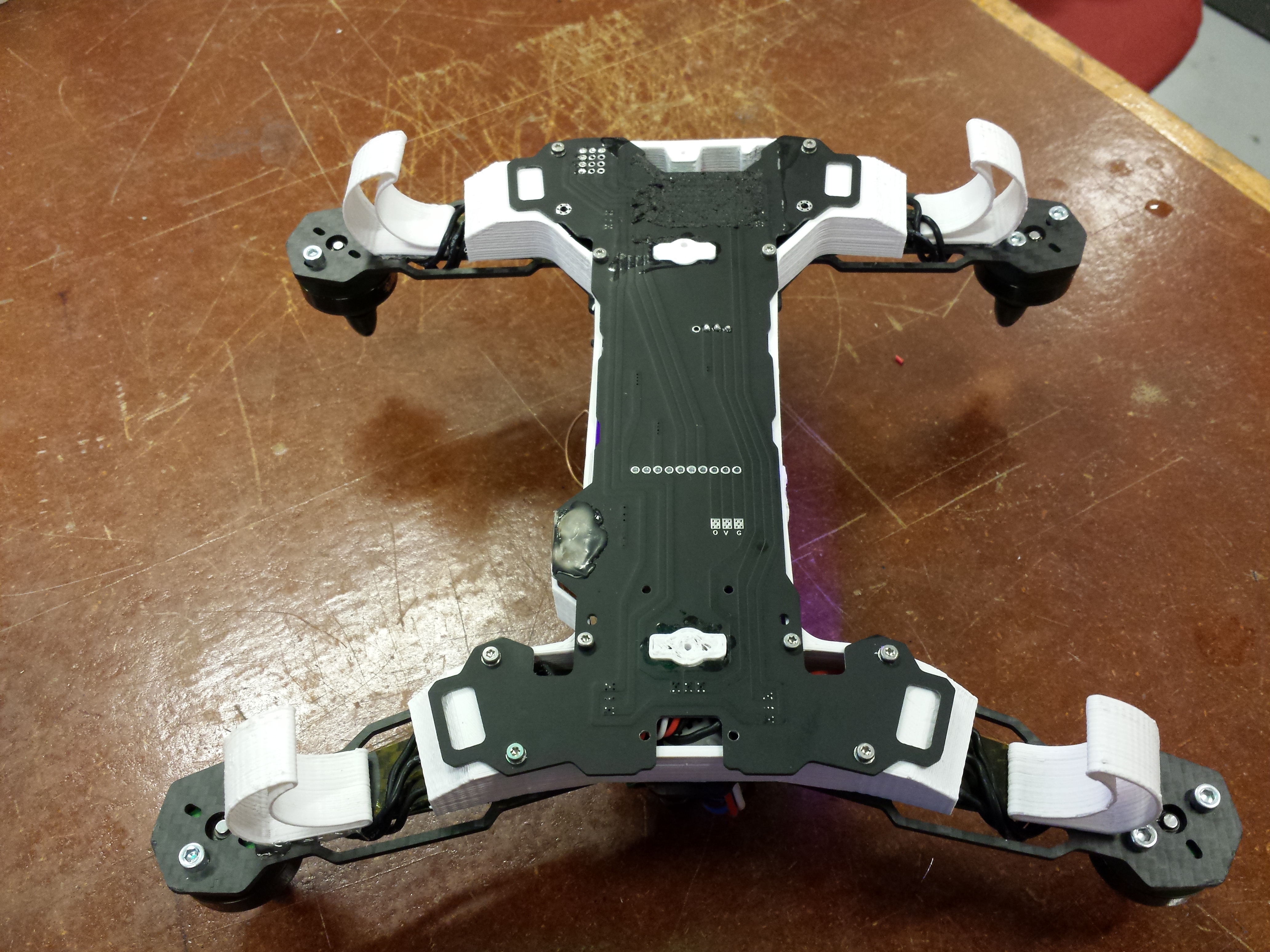
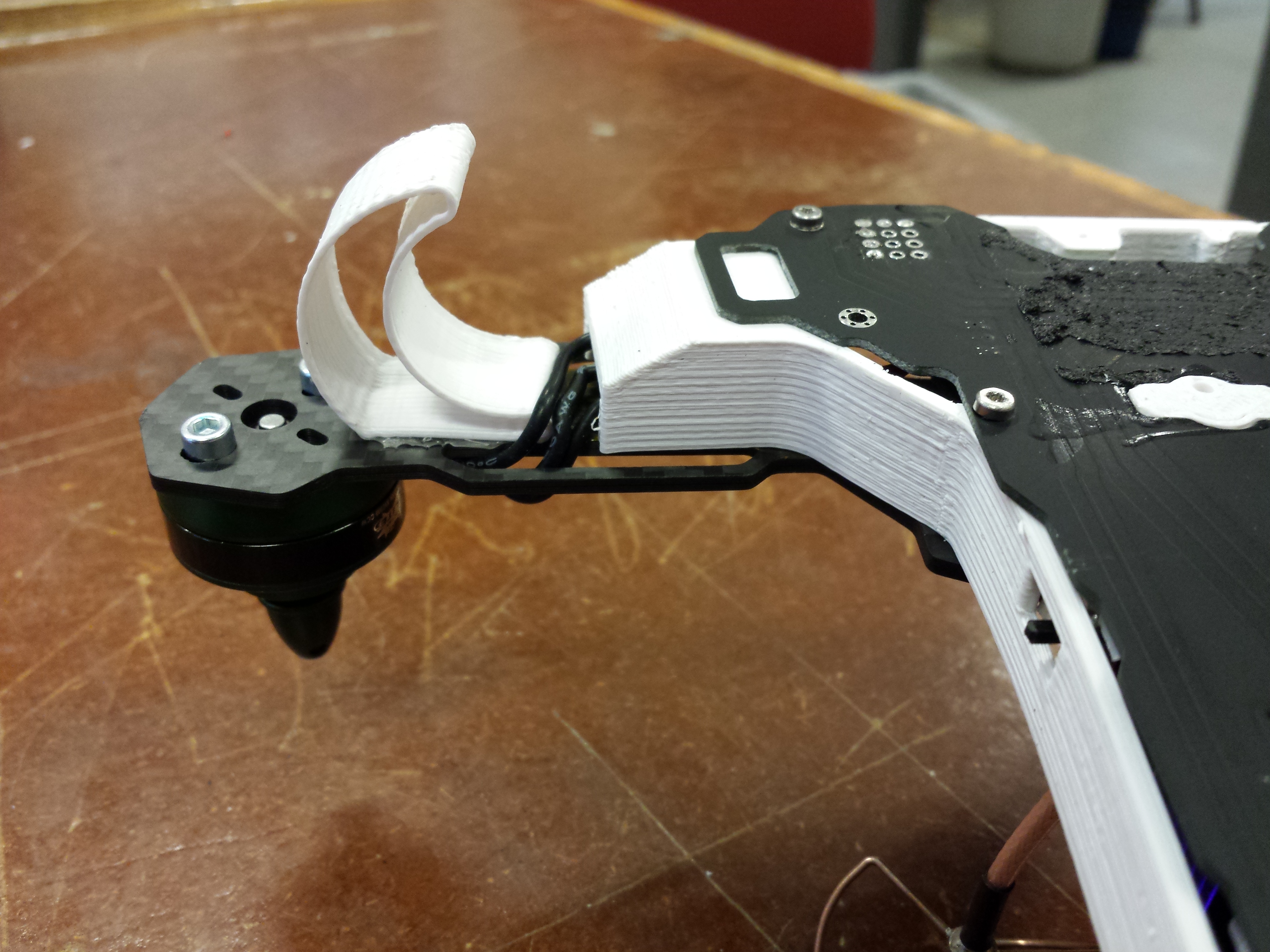
Connecting stuff
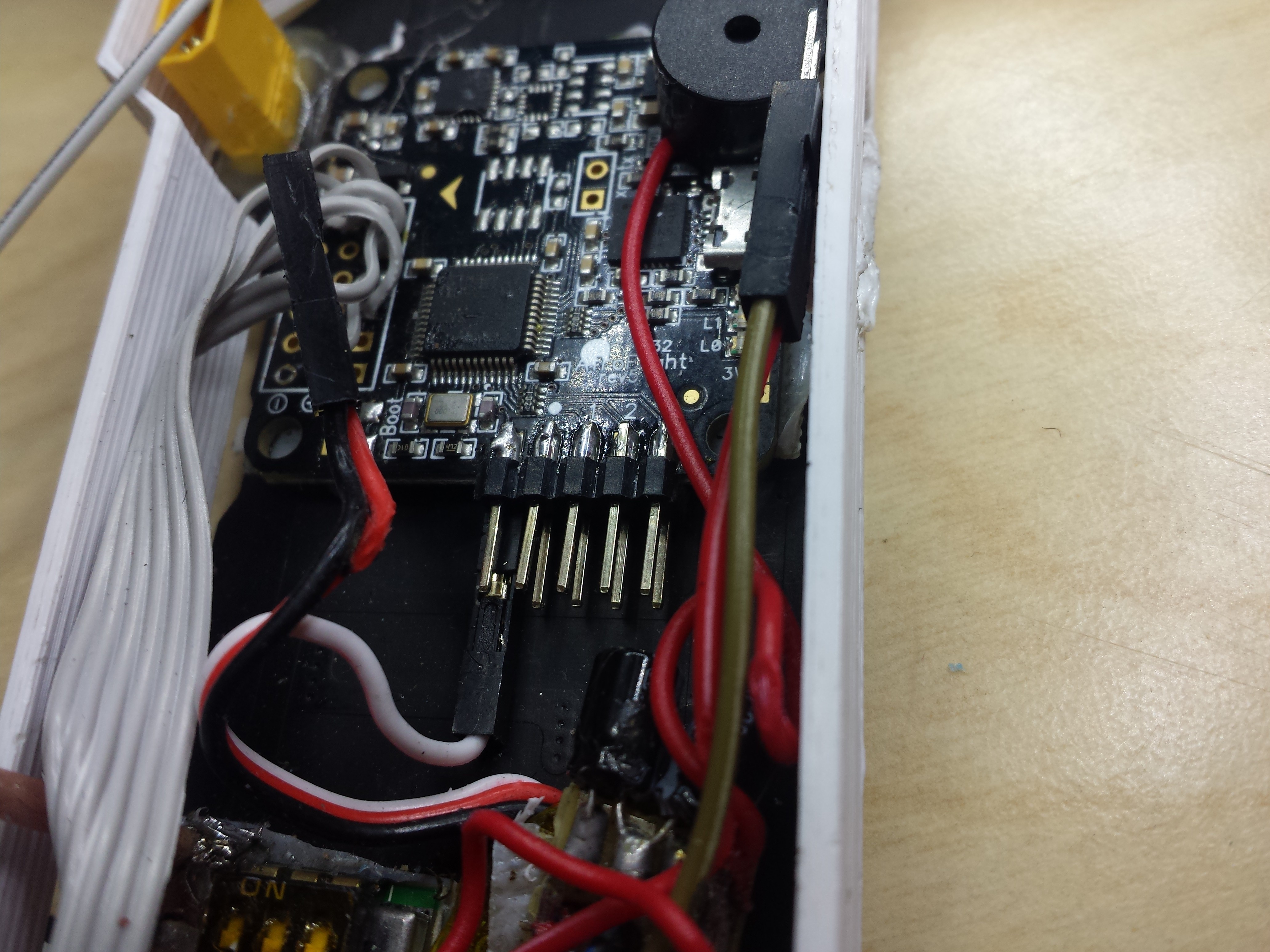
The input of the logic inverter comes from the reciever, and the output goes to the pin marked “5” on the backside of the naze32.
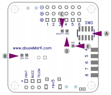
The pad marked “5” to the right is the one to connect the inverted SBUS signal.
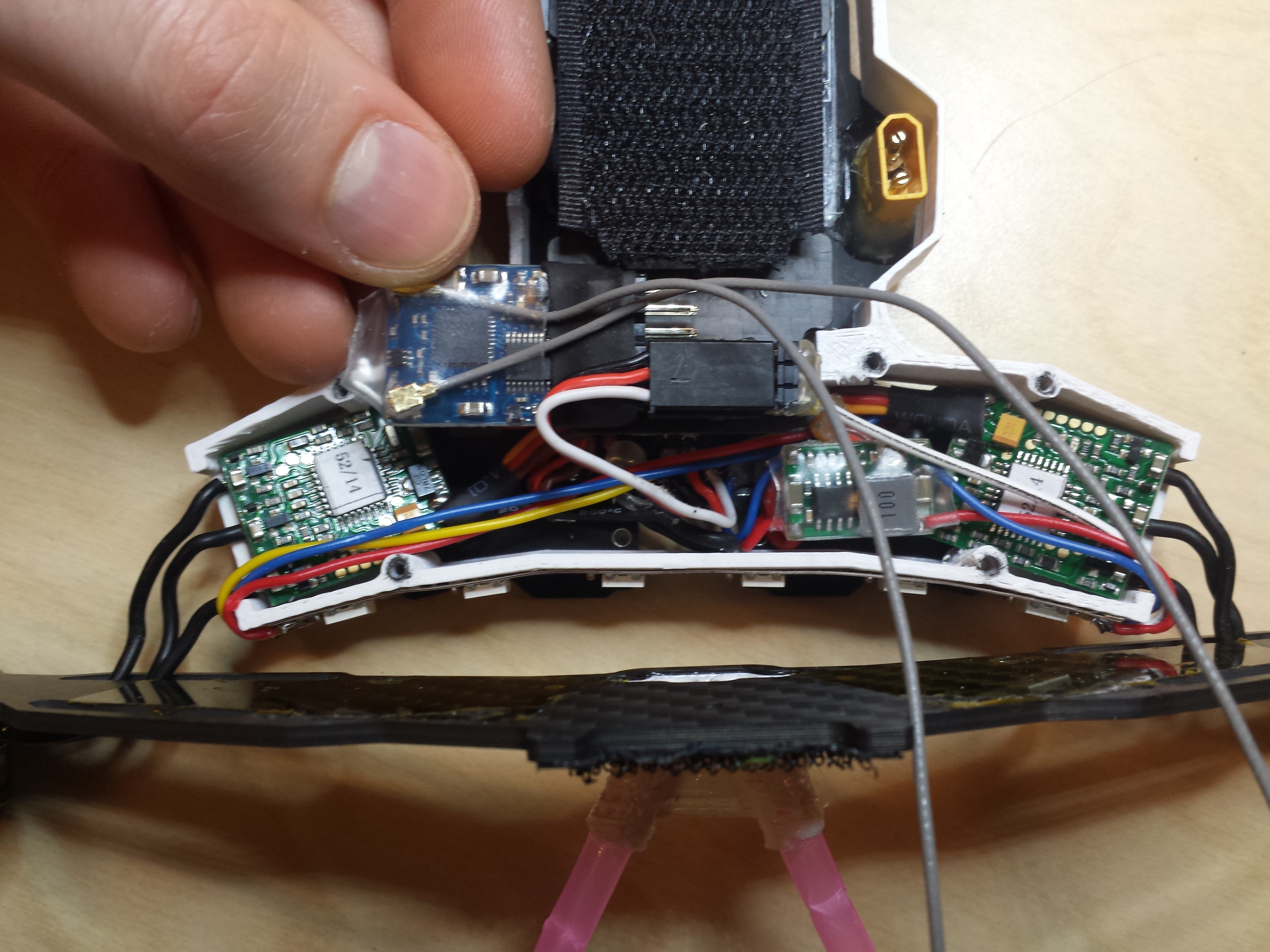
-
- the white cable connected to the naze32 is where the SBUS signal goes in
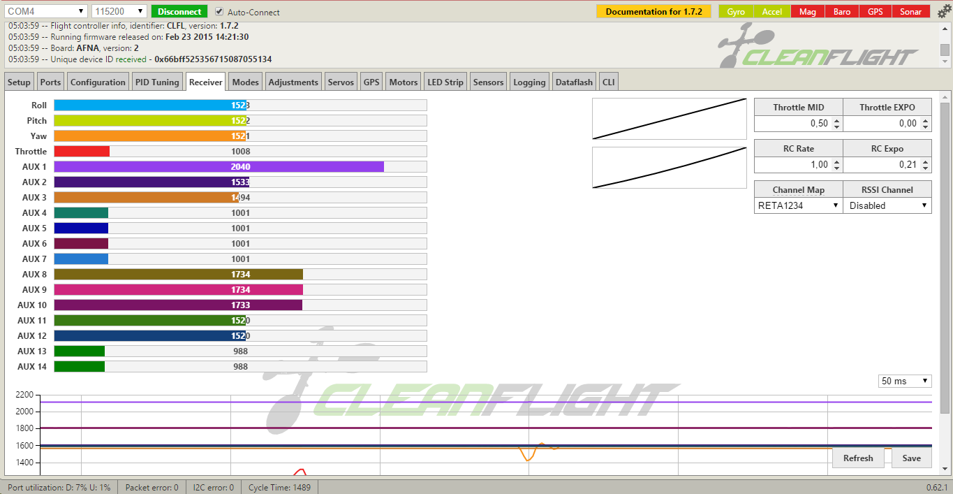
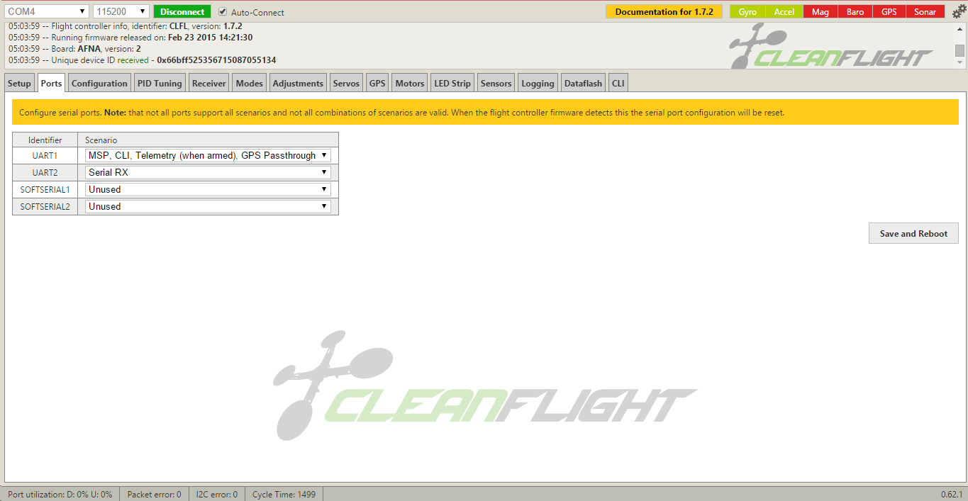
4. How to set up Naze32 in Cleanflight to use the SBUS as rc input
- In the Ports tab, set UART2 to SerialRx
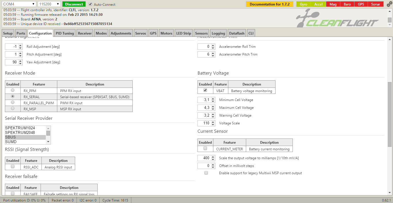
- In the Configuration tab, click the RX_SERIAL radiobutton and select SBUS from the “Serial Receiver Provider” list. don’t use Softserial.
- Check if it works in the Receiver Tab!
-
- no signal recieved
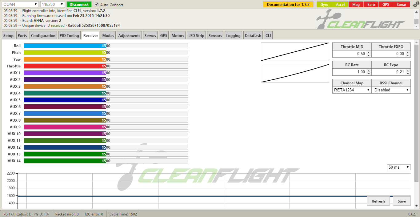
-

- it works!